Introduction: The Universal Structural Component
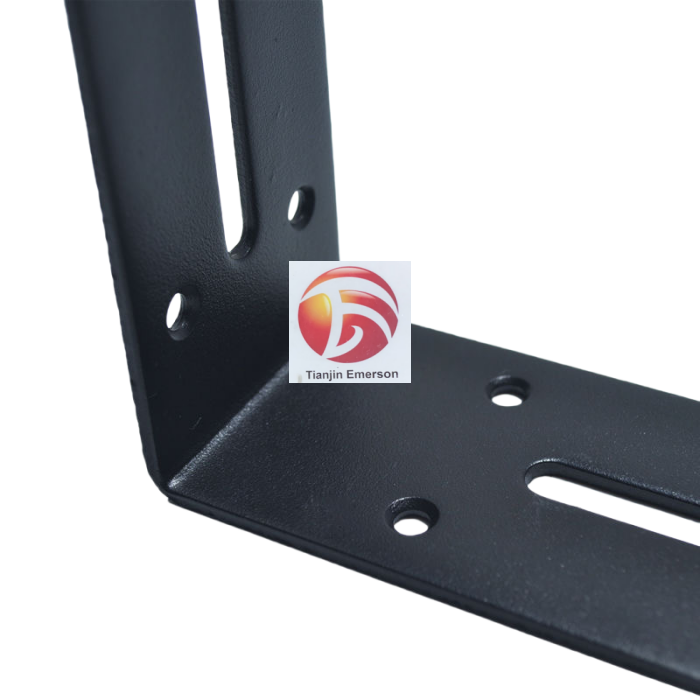
Steel brackets are among the most ubiquitous yet essential components in modern engineering and construction. Walk through any factory, industrial facility, or building site, and you will find them in countless forms—L-shaped, Z-shaped, U-shaped, triangular, welded, or bent. These seemingly simple components serve as the critical interface between structural elements, transferring loads, providing reinforcement, and ensuring stability across a vast range of applications. From supporting conveyor systems and mounting medical devices to bracing solar panels and securing electronics, steel brackets are the unsung heroes of structural integrity. Understanding their diverse application areas and the critical precautions required during cutting and bending is essential for engineers, fabricators, and procurement professionals seeking to produce high-quality, reliable components.
Major Application Areas of Steel Brackets
The versatility of steel brackets is reflected in their extensive use across multiple industries and infrastructure sectors.
In construction and building, steel brackets are fundamental to structural framing. Galvanised angle brackets are extensively used to reinforce joints, secure framing elements, and provide structural support for decks, pergolas, and building frameworks. They connect steel beams and columns in commercial and industrial construction, reinforce building corners, and connect timber or steel structural elements. In rainscreen façade systems, specialized stainless-steel brackets serve as the load-bearing connection between the building substrate and the façade substructure, supporting both single-layer and double-layer configurations while enabling faster, simpler, and safer installation.
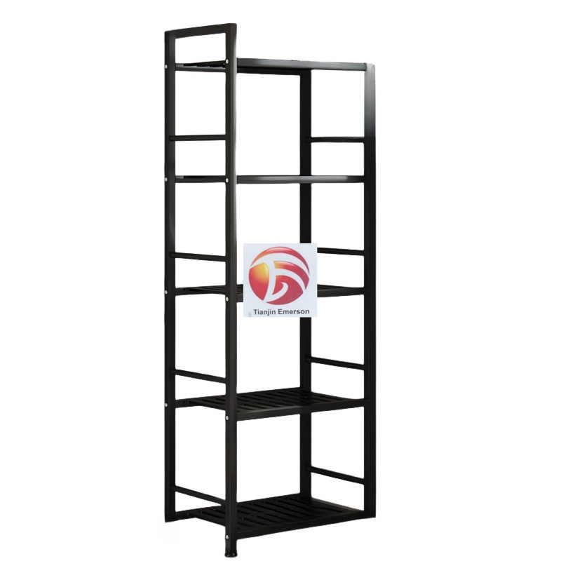
In industrial and manufacturing settings, steel brackets provide reliable angular connections for machinery, equipment, and infrastructure. They secure heavy equipment, support piping systems, and serve as fundamental support components in manufacturing and logistics operations. Heavy-duty industrial brackets provide reliable structural support for fixed and flexible joints in construction, manufacturing, and machinery. In warehouse and logistics facilities, brackets are essential for assembling storage racks and shelving systems.
In infrastructure and civil engineering, steel brackets play critical roles in bridges, tunnels, and public infrastructure. They reinforce beams, columns, and trusses in building frameworks and public works. Steel brackets are used as load-bearing elements in bridge construction, including large-span steel box girders and pedestrian bridges. In tunnel construction, specialized U-shaped steel brackets provide stable support and enhance worker safety. Steel pipe brackets are applied in water conservancy projects, excavation, and artificial island construction. Stair handrails, pipe supports, and bridge reinforcement all depend on properly fabricated steel brackets.
In transportation and specialized equipment, steel brackets are indispensable. In elevator manufacturing, guide rail brackets ensure smooth elevator operation. In automotive manufacturing, brackets secure components and assemblies. Heavy-duty galvanised brackets are engineered for outdoor use and OEM fabrication, offering unmatched durability and corrosion resistance.
Critical Precautions for Cutting Steel Brackets
The precision of the cutting operation directly determines the quality and performance of the finished bracket. Several critical considerations must be addressed during cutting.
Material selection and compatibility are paramount. Laser cutting is compatible with many materials including aluminium, stainless steel, tungsten, titanium, copper, and brass, but it is limited to cutting thinner gauges. For steel brackets, the material thickness must fall within the capabilities of the cutting equipment. For 1/8-inch steel, a 45-amp nozzle is typically required. Hot-rolled steel with heavy mill scale can cause inconsistent cutting because the scale absorbs laser energy differently than bare steel; pickled and oiled (HRP&O) steel is therefore preferred for consistent results.
Hole size and placement require careful attention. Laser cutting can cut holes very precisely, but there is a limit on how small holes can be made cleanly. A general rule is that the hole diameter should not be smaller than the material thickness. More critically, holes should be placed away from bend lines. A hole placed within approximately four times the material thickness of a bend line will stretch and distort during bending—a perfect circle on the CAD model will arrive at assembly as a warped, useless oval. Holes should be located away from high-stress areas and should not be placed in the immediate vicinity of the bending line.
Kerf and tolerance management is essential for achieving proper fit. Kerf refers to the width of material removed by the laser cut and must be factored into design dimensions. Depending on the laser technology used, tolerances may range from +/-0.0254mm to 0.127mm. For precision applications, positioning accuracy of ±0.02mm/m and repeatability of ±0.01mm are achievable with advanced fibre laser systems. When designing features that must fit together, designers should adjust dimensions by half the kerf value to ensure parts fit correctly after cutting.
Critical Precautions for Bending Steel Brackets
Bending transforms flat cut blanks into three-dimensional structural components, but this process introduces several challenges that must be managed to produce high-quality brackets.
Springback compensation is perhaps the most critical consideration in steel bracket bending. Springback is the phenomenon where material partially reverts to its original configuration after bending due to the relief of internal stresses. To achieve a true 90-degree angle, the material must be bent past 90 degrees—often to 92 or 93 degrees, depending on the material. For stainless steel 304 or 316, the springback effect is particularly pronounced, requiring angle compensation of 1–3 degrees depending on thickness. Advanced CNC bending systems use proprietary springback compensation algorithms that factor in distinct stress distributions on each bend line, achieving matching reverse angles within ±0.3 degrees. Without proper compensation, the final bracket will not meet dimensional specifications, requiring rework or scrapping.
Minimum bend radius and tooling selection must be carefully considered. Different materials have minimum bend radii they can withstand without cracking. A sharp internal radius on high-strength stainless steel requires higher tonnage, which means bigger machines and higher costs. For example, specifying a 0.5mm radius on 3mm stainless steel will rapidly wear out tooling. A better solution is to add a radius to the cut area that will be bent or formed to avoid potential design issues. The material's minimum flange support region must also be respected; material within this region will contact the tooling during bending and can cause defects.
Bend sequence and clearance planning are essential for multi-bend brackets. For parts with multiple bends in tight spaces, sectional punches can provide necessary clearance. Without proper sequence planning, subsequent bends can interfere with previous ones, and fastener heads may not have adequate clearance for assembly. Designers must account for bend allowance—the stretching on the outside and compression on the inside of a bend—to ensure the finished bracket matches dimensional requirements. The K-factor is essential for calculating springback and predicting final bend angle accuracy.
Surface protection and handling are particularly important for aesthetic or coated brackets. Aluminium brackets require soft die covers or polyurethane film to prevent dent marks. Even stainless steel brackets can suffer from surface scratches if handling is not carefully managed. The holes in the bracket should be located away from high-stress areas and not in the immediate vicinity of the bending line. Proper finishing—whether powder coating, galvanising, or other treatments—should be applied after cutting and bending to ensure complete coverage and protection.
Integration of Cutting and Bending for Quality Assurance
The physical act of cutting and bending is only the baseline; the real challenge lies in managing the interfaces between these operations. A design that fails to account for material thickness, grain direction, and springback may survive a prototype run but will inevitably drift out of specification during volume production. Industry data shows that roughly 70% of sheet metal production problems—and the resulting 25% to 40% cost increases—come from bend-radius violations, impossible tolerances, and finishing complications. By integrating CAD design, precision laser cutting with appropriate kerf and hole placement, and CNC bending with proper springback compensation and tooling selection, fabricators can produce steel brackets that are dimensionally accurate, structurally sound, and ready for their intended applications across construction, infrastructure, and industrial manufacturing.